Basic Control
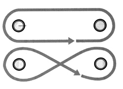
Ideally, the speed of a DC motor is proportional to the supply voltage. Accordingly, to control the velocity of the RC car, the on board speed controller varies the motor's voltage from -7.2 to +7.2 volts through the use of a pulse-width modulated signal. To accomplish velocity control without the remote control system's PWM signal, the Arduino Mega micro-controller, in combination with the servo library, was used. Similarly steering was controlled with a PWM fed to the steering servos. Fortunately, no additional power-supply was needed since the RC circuits run at a similar enough voltage (at least when the battery is charged ;) ). With this basic control, linear motion was accomplished, followed by circular motion, and finally a technical figure eight pattern.

Measuring Displacement From Voltage
The car's DC motor acts as a generator, where energy generated by the inertia of the car. By adding a resistor to the signal, its current is limited before being fed into the analog to digital converter. From this signal the velocity is obtained. Integrating this signal over time gives the car's displacement. As a note, the units used throughout were not exactly SI.
![]() &
& ![]()
As seen in the video, the car is instructed to first move forward a given distance then coast. During these opperations, this distance is summed and saved in memory. Next the car is instructed to move backward at a speed proportional to the remaining distance to be traveled (even if that is a forward movement). Since the loop runs indefinitely, if the car were to be moved at this point, the car would attempt to return to the final position.

Conclusion
The PI control system was fairly accurate. Unfortunately, sinc the error increased with the speed, high speed tests where not possible. The control system could have been greatly improved upon by adding an encoder or another DC motor which would act as an independent transducer. As for basic control, this project was a great success and gave insight to how the RC car's components work.
