
Introduction
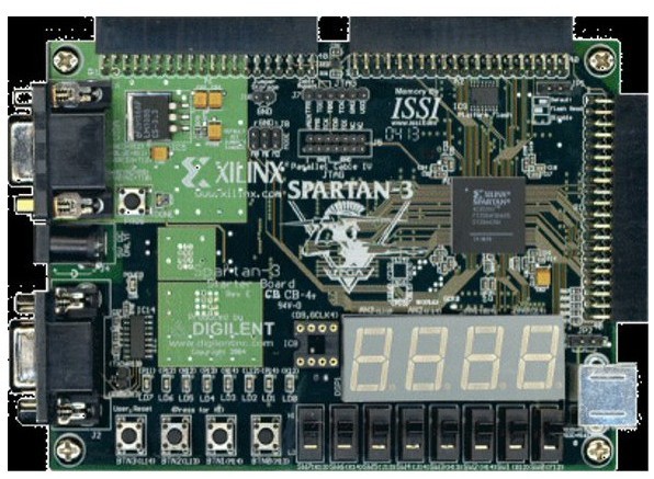
As an introduction to Xilinks FPGAs design, I began a tutorial which involved building a counter which output to a seven segment display. The software used was ISE design suite 13.2 and the FPGA used was part of a Spartan 3 development board (~$140).
The ASIC Solution
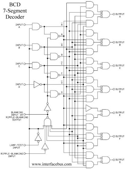
Previously, ASICs or application-specific integrated circuits where the popular way to do digital logic. Similar to the binary counter project, digital logic is employed to maintain a count as well as to decode the resulting counter value to a readable output. The digital logic that fulfills these roles resides on integrated circuits called binary counters and decoders, respectively. In their physical forms, as ASICs, these chips perform logical operations with a permanent arrangement of gates. For example, a binary decimal coded to seven segment decoder looks like the following.
Enter the FPGA
FPGA is an initialization for field programmable gate array which implies that the arrangement of gates (example seen in the schematic above) can be configured dynamically. This improves time to market and cuts down on development costs while providing endless amounts of customization and rapid testing. To describe the desired logic which is to be programmed to the FPGA, a hardware descriptive language or HDL is used. For this project, the Verilog HDL was used.
Relatively simple logical ICs like the decoder are fairly easy to recreate in code while other logical ICs are not practical to re-develop in a “soft” format. Fortunately, in the world of FPGAs, IP cores (intellectual property cores) can be purchased and programmed to the FPGA. In fact, many IP cores are free. IP cores range in complexity and include many popular digital logic components such as micro-controllers, adders, decoders, VGA processing modules and more. With proper training, one could develop a system on chip solution in which a single FPGA provides as all major system functions like RAM, I/O, and Computation. Aside from being field programmable, this type of design reduces hardware complexity and chip count alike.
Conclusion
After completing the tutorial and expanding on the design substantially, the result is a resettable 4 digit seven segment counter that can operate at 8 different count speeds ranging from 1Hz to 1kHz. One of the biggest obstacles was multiplexing the display, necessitated by the nature of the seven segment display interface. This obstacle was overcome through the use of another clock which controls the previous and next digit to be written.The finished counter is showcased in the YouTube video above and is implemented entirely using Verilog.